I have acquired the Graupner MC-22s RC radio since the end of the year 2007.
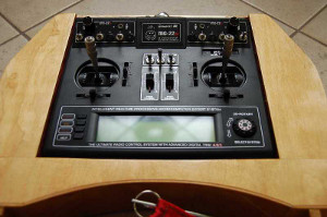
MC-22s Front View
I found some useful information about it’s “hidden” capabilities after some period of time. It has following features, not used at purchase stage:
- Additional controls = switches / potentiometers
- Teacher (trainer) <-> student (pupil) connection (DSC)
- Serial port communication for saving and loading model storage to / from PC
RS232 (serial port) communicating protocol has following parameters: 4800Bd, 8 bits, even parity, 1 stop bit
You can use software (mc-xx-BackUp) on http://www.zuckers.net/mcxxbackup/ for backup / restore Your RC models.
Viewer of acquired data (MCEdit) is provided on http://www.obbl-net.de/mcedit.html by Martin Opel, thanks to him for excellent work !
All of these possibilities I have realized to appear on the top panel.
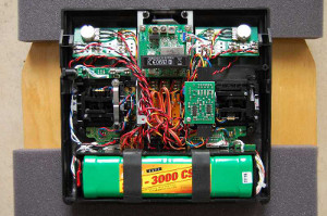
MC-22s Back View
I added four PCBs inside the MC-22s.
First one serves as adapter between main board and my interface (I wasn’t able to get original connector). It provides possibility to mount very cheap and available connector http://www.gme.cz/cz/index.php?product=832-083. It has 15 pins, so I had to cut one pin away. Very important is 2mm distance between pins.
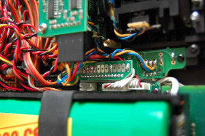
MC-22s Adapter Board
Between adapter and interface, there are six wires. These wires begin on the adapter board (pins are named from left to right as You can see at the picture … soldered pads):
- PIN03: RS232 RX – input
- PIN04: RS232 TX – output / input (if not used by radio)
- PIN05: DSC OUT – output of PPM signal (student)
- PIN06: DSC IN – input of PPM signal (teacher)
- PIN10: GND – ground
- PIN14: +5V – power supply
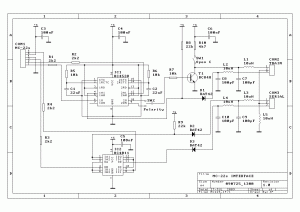
MC-22s interface board scheme
The other ends of wires are connected to the interface PCB. As You can see at the scheme picture, there is following sequence of pins (on the PCB picture below this is connector on the right, pins are numbered from below to top):
- PIN01: DSC output (to DSC input of MC-22s – pin 06)
- PIN02: DSC input (from DSC output of MC-22s – pin 05)
- PIN03: RS232 output (to RS232 input of MC-22s – pin 03)
- PIN04: GND (pin 10)
- PIN05: +5V (pin 14)
- PIN06: RS232 input (from RS232 output of MC22s – pin 04)
It consists of 4x NOR gates, which serves as separators from/to outspace and 4538 – dual precision monostable multivibrator. It’s task is to prolong or shorten DSC pulses from or into the radio. Pulses are set to approximately 154μs long (0.7 * R * C) in the result. This multivibrator is required mainly in case of other RC radios types with different length of transmitted pulses. Switch SW1 can be done as jumper (I had some special switch, it is blue one with red lever at the bottom of PCB), switch SW2 is realized as as soldered shunt – join only one of them, please! You can use HC4001 instead of HC4011, if You want (as me). Interface board is described in the file MC22s_IFC_PCB.pdf. There is drilling data available for download too.
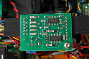
MC-22s Interface Board
Interface board is then providing DSC input and output together with RS232 input and output pins. This PCB is wired with connectors installed on the last type of boards – connection boards, described in the MC22s_ADPT.pdf file as well as adapter board.
There are two connection boards, one from each other are mirrored. The distances of pads are designed in opposite of MC-22s top panel holes. Again, there is file with data of drilling available for download.
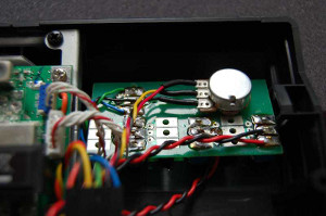
MC-22s Connection Board
